This is a great read. Not so useful for guitarists, perhaps, but it's good to be familiar with this info.
http://www.rane.com/note110.html
Sunday, October 19, 2014
MPS Iron
I got a Musical Power Supplies OT40PP for the Rocket build. I have one of MPS's earlier offshore versions of this OT in Bodie and it works well in that amp.
This new model is made in the US with M6 steel, 4/8/16 ohm taps on the secondary, and 4k2 and 3k3 primaries.
It's a great chunk of iron at a great price. No idea who's doing the winding, but this guy knows how to spec his iron. I'm super happy, especially compared to the stock Crate iron.
It's kind of odd to think how similar the Fender 5F6A, Marshall JTM45 & Plexi, Vox AC30 (Trainwreck Rocket), and Sunn Model T are. Okay, the first two really aren't much of a surprise, and there are countless other examples... I guess it's just a really popular topography.
I can kind of see it, but it's just not doing much for me. Maybe with a different tone stack or some NFB. Just a little more midrange and a little less bass would go a long way.
Sunday, September 14, 2014
Silverface reverb
Okay, so during the silverface era, CBS decided to beat the living hell out of the reverb driver, lowering the cathode bias resistor to 470R. Easy fix here, just replace the cathode bias resistor with the blackface value of 2k2 bypassed with a 25uF cap.
Another nifty trick is to replace the reverb driver's grid leak with a pot, aka a dwell control. That's how it was labeled on the original reverb units, though it's a little disingenuous as it doesn't control how long it takes for the reverb to decay (I mean, how could it, right?) but instead it controls the level of signal sent to the driver, with the existing reverb pot controlling the level of signal coming off the recovery gain stage. With a dwell pot, you can dial in a much more subtle reverb sound that's more dynamic.
I just put the dwell pot in the place of the humdinger which had fried ages ago due to a heater-to-plate short. While I'd like a proper humdinger, a pair of 100R resistors off the pilot light is better than a blown pot!
Saturday, August 30, 2014
Bodie Test Recording
https://soundcloud.com/paulpampspgh-1/bodie-test-140830
Here's a quick test of the newest version of Bodie. I'll update the schematic soon. Basically just cascaded the first two stages instead of running them in parallel. A couple more tweaks to come too.
Here's a quick test of the newest version of Bodie. I'll update the schematic soon. Basically just cascaded the first two stages instead of running them in parallel. A couple more tweaks to come too.
Wednesday, August 6, 2014
Final-ish Rockette Schematic
The previous .sch files appear to be lost, so I drew up a new one showing the current schematic of the Rockette.

Some of the parts values might be off, but dig that normal channel. Super useful.
Some of the parts values might be off, but dig that normal channel. Super useful.
Saturday, July 5, 2014
Rocket in the pocket
So, I got the Rocket finished a while ago. I decided to add a Vox "normal channel" by using the spare gain stage through a gain pot into the other side of the phase inverter. It took a little tweaking, namely an additional grid leak, stopper, and coupling cap, but it's worth it.
Drive is reduced slightly on the TB channel, which is fine, and the single gain stage normal channel can drive the amp into overdrive just fine. The "cut" control still works for both channels, of course, since it's after the phase inverter.
I used the other side of the PI (the second triode's grid, which is usually grounded with a large cap) because the two channels are out of phase. I kept the two channels permanently bridged because I didn't feel like adding three input jacks and the ability to blend the two channels is great. You can dial in some mids to get a thicker sound than a typical Vox, or use either channel independently.
It's not a revolutionary idea, I mean, the AC30 uses the PI to mix the normal and overdrive channels with the reverb/trem signals on the second grid. Typically the normal and tb channels can't be bridged, so this is novel, at least, while bringing the pi closer to the original.
I'm tempted to add channel switching by using an on/off/on SPDT to shunt either grid to ground with a large cap. Heck, why not do it with a relay and footswitch? Ah, but how to power a relay?
Unfortunately, the rocket's going to be out of commission for a while due to a shorted output tube, but if anyone is looking for ideas about the Trainwreck "unused triode" I just have two words: normal channel.
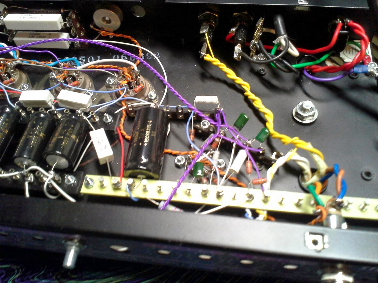
Oh yeah, and here's a nasty gut shot as I still haven't drawn an updated schematic!
I also moved the hv fuse to the front panel because it just made way more sense there from a wiring perspective.

Drive is reduced slightly on the TB channel, which is fine, and the single gain stage normal channel can drive the amp into overdrive just fine. The "cut" control still works for both channels, of course, since it's after the phase inverter.
I used the other side of the PI (the second triode's grid, which is usually grounded with a large cap) because the two channels are out of phase. I kept the two channels permanently bridged because I didn't feel like adding three input jacks and the ability to blend the two channels is great. You can dial in some mids to get a thicker sound than a typical Vox, or use either channel independently.
It's not a revolutionary idea, I mean, the AC30 uses the PI to mix the normal and overdrive channels with the reverb/trem signals on the second grid. Typically the normal and tb channels can't be bridged, so this is novel, at least, while bringing the pi closer to the original.
I'm tempted to add channel switching by using an on/off/on SPDT to shunt either grid to ground with a large cap. Heck, why not do it with a relay and footswitch? Ah, but how to power a relay?
Unfortunately, the rocket's going to be out of commission for a while due to a shorted output tube, but if anyone is looking for ideas about the Trainwreck "unused triode" I just have two words: normal channel.
Oh yeah, and here's a nasty gut shot as I still haven't drawn an updated schematic!
I also moved the hv fuse to the front panel because it just made way more sense there from a wiring perspective.

The last word on "ultralinear" Fenders
I'm so amazingly lazy, I'm just going to copy/paste what I posted at MEF:
Finally took some measurements.
I pulled two tubes because my dummy load is only 100W.
Idle conditions:
Va = 487V
Ia = 29.9 mA (49% idle dissipation; a little cold, sure)
at full clean output: 24.1V into 10.1 ohm resistor for 57.5W
So for the screens we have, at full output:
27.3Vac across 1.991k screen resistor = It = .0137 A
DC ammeter in series with screen resistor = .00892 A
And the equation for screen dissipation in distributed load connection is:
P = EI - ei
where e = (1/2)(Ns/Np)sqrt(RlPo)
and i = sqrt(It^2 - I^2)
Sooooo:
e = (1/2)(.125)sqrt(10.1R * 57.5W) = 1.506 V
i = sqrt(.0137^2 - .00892^2) = .0104 A
P = (487 V)(.00912 A) - (1.506 V)(.0104 A) = 4.43 W
...which is a whole pants load different from (487V)(.00912A) = 4.44 W
But considering the maximum dissipation for a 6L6GC screen is 5W, I'd say with 2k screen stoppers we're in the clear. Unless, of course, I'm doing things horrendously wrong. It would be interesting to repeat this with different values of screen stopper; I kind of doubt that I lucked into such a good value of screen stopper.
In lieu of a thermocouple ammeter, I measured the AC voltage across the screen stopper. This is probably a significant source of error. The result does seem reasonable, when comparing how the screen voltage swings at a 12.5% tap instead of a 40% tap. I was expecting to see a minor reduction in screen dissipation due to power being dissipated in the load, and this is what I found, but I guess I was hoping it would be a little more.
On top of that, my plate voltage is lower than what I've measured previously, and the bias is on the cold side.
Now, what dawned on me after I posted this is that these calculations are independent of the value of the screen stopper. That is, without a screen stopper at all, the maximum screen dissipation at full output is roughly 4.5W. At least a hundred ohms should be used as a screen stopper anyway, to prevent oscillation.
I'm not sure what'd going to happen during overdrive, so a hefty screen stopper is probably still a good idea. Even with 2k stoppers, this bad boy'll put out 115W of clean power before clipping. Even if it did put out a clean 135W (mfg ratings are always dubious), it would be virtually indistinguishable from the 85W an earlier BF/SF Twin would put out.
Tl;dr - don't worry about it. 6L6s are just fine. That's not to say a pair of KT88s wouldn't be fun too, but there's no need to worry.
I'd like to get measurements under overdrive, but that'll have to wait until I get a true RMS meter.
Here's a link to the thread where I originally posted: Music Electronics Forum
Thursday, May 15, 2014
NGD - 2013 Gibson SGJ
Okay, so not particularly amp related, but I need somewhere to park these images.


Tuesday, April 1, 2014
PI
So! Finished the power tube wiring. Used one bias resistor for the inner pair and one for the outer, so one set can be pulled if need be. The tubes are biasing at 13W and 13.5W, which should be fine.
I also got the PI wired - I promise it's in there somewhere. Pretty much as far away from the power tubes as possible. Next time, I'm totally drilling the chassis; I'm lucky it's quiet.
Well, that's not entirely true. I did my best with the grounding and layout that I could. And the preamp isn't wired in yet, but compared to the "are you sure it's on" Dynaco gold standard for quiet power amps, this guy's not quite there. Compared to my Twin with the master on 0, though, the Rockette is an order of magnitude quieter. And it's not even connected to the chassis yet!
Okay, enough. I thought that the massive leads to the output tube grids would be a death sentence, and I'm glad they're not. Also, those chicklets are totally 630v film caps. I vaguely remember Mouser being out of the particular caps I wanted and apparently I never followed through on ordering them. Same reason there are some different 470k metal films in there.
Oh well. I'm also running out of teflon wire, so the color scheme is probably going to get even wackier in the preamp.
I really need to give this thing a different name.
I have some cascode wackiness planned for the unused triode in V1 so I can get both the AC30 top boost channel and something like the AC30/4 normal channel at the same time. Bridged, even. I'll decide if that's worth it after I get the stock schematic working.
Or I could still try the "jumpered Plexi" thing. I should at least try the amp as Ken Fisher might've designed it first.
Maybe that's some variant of "blind urge to mod" syndrome. "Blind urge to make a design more 'original'" syndrome. Eh. It's my basement; I make the rules!
Saturday, March 22, 2014
The five percent nation of filter caps
Finally got a little more work done on the Rockette. I need to think of a better name.
Anyway.
Got the power amp finished, except for the grid leaks. Maybe I will put that PPIMV in after all. The PI tube is all the way across the chassis so I'll probably need shielded cable anyway.
Also finished wiring in the filter caps. I don't like turrets; tag strips have ruined me forever.
It's crazy how time-consuming this is when you're not painting by the numbers. If I had a board of the preamp components that I could just plop in, I'd be done by now.
Hopefully I can avoid noise problems, because fixing them is going to be a bear. The "distributed star" grounding is going to help, and I should be able to attach the components to the preamp sockets in a "bicycle spoke" pattern also, which is pretty much ideal.
Time will tell, but I'm optimistic.

Thursday, March 13, 2014
Incremental progress
Not much time spent today, but I got the grid stoppers in place and the screens connected.
Really wish I had a chassis-mount resistor for biasing the power tubes, but I think I'm just going to plow ahead with the cement blocks I have on hand.
I did spend a little line on the load line for this 3k OT. Probably the only thing I ever thought "when am I ever going to use this" about in college was graphical analysis, rulers and pencils and such. "We've got computers now!"
Har, har.
Little did I know I'd be trying to extrapolate anode curves for a 6V6 at 350V, for fun.
...I gotta learn Spice.

Tuesday, March 11, 2014
I've got the power (supply) (almost)
So, pretty wild that I've had another productive day. Didn't have a ton of time, but still managed to get the power supply laid out and the power tubes halfway wired.
Oh, and I finally measured the Crate OT: 3k plate-to-plate (to 8, 16 ohms) which probably seems low for a guitar amp, but I'm thinking it'll be pretty close to ideal. I'll have to plot some loadlines, just to be sure.

Oh, and I finally measured the Crate OT: 3k plate-to-plate (to 8, 16 ohms) which probably seems low for a guitar amp, but I'm thinking it'll be pretty close to ideal. I'll have to plot some loadlines, just to be sure.

Monday, March 10, 2014
Bridge to B+
Ugly, sure. But it works. For the first test fire, I forgot the bleeder. Yay, 375V! Um... Where's that cap drainer?!
I did leave the B+ fuse on the back panel. That whole corner of the chassis is completely off limits for any signal wiring. AC radiating everywhere.
Next donor chassis... I've gotta drill it. This is just silly.

I did leave the B+ fuse on the back panel. That whole corner of the chassis is completely off limits for any signal wiring. AC radiating everywhere.
Next donor chassis... I've gotta drill it. This is just silly.

Sunday, March 9, 2014
Rockette - more wiring
So, I got the PT primary wired up. The safety is wired to its own chassis connection, and the purple is just a static shield for the PT.
No rectifier yet, but we're getting 273V AC, both unloaded and with the tubes in (heater load). Forgot to check what the heater sags to, but unloaded it's at 6.8V AC, which is fine.
Admirable performance from a PT sold as 250V. Added bonus: it's rated for 100VA at 50 Hz. Long story short, it should be able to supply much more current than the amp can draw. Which is great, because how guitar amp PTs have been sized in the past irks me.
To that end, I don't think I'm going to install a sag resistor. At least not initially. I might abandon cathode bias later on too. We'll see how punchy it is, and if it's not enough I'll go from there.
I think I'm going to mount the B+ fuse internally. As much as I like the pretty fuse holder on the back, it's just going to be inconvenient for wiring. Same reason I installed a Carling instead of using the front panel power switch it came with.
Slow and steady...

Sunday, March 2, 2014
Heaters
...I hate wiring heaters.
I'm hoping having the heaters run perpendicular to most of the signal wiring + the correct approach to the sockets + an elevated humdinger should add up to no hum, but I guess we'll find out.
I probably should make a genuine elevation node for the heaters instead of just referencing the power tubes' cathodes, what with the DC cathode follower raising Vhk on v2b into dangerous territory.
Kind of moot until I can figure out where to put the bridge rectifier and the reservoir & screen supply caps.
The rest just falls into place though.

Sunday, January 12, 2014
Ultralinear vs Distributed Load in the Late 70s through Early 80s Fender Twin Reverb
Okay, I kind of played it fast and loose on the technical side with my last two updates concerning the "Ultralinear" Twin.
If you'd like a primer written by someone much more well versed in the effects of connecting the screens to taps on the OT, read this: Oestex - Ultra-Linear
Say we're designing an amp, and we want to connect the screens to taps on the primary side of the OT. If we connect the screen taps to the OT center tap (0% of the primary turns), we get pentode operation, albeit with no ripple filtering. if we instead connect the screen taps to the plate taps (100% of the primary turns) we have triode operation. Anywhere in between we get what is known as "distributed load" operation, which has performance somewhere in between pentode mode and triode mode.
Pentode mode has higher output, but also higher distortion. This is how nearly all of guitar amps are typically connected. Certainly all amps you can buy in the store. Many guitar amps have a "half power" switch, sometimes properly labeled as a "triode/pentode" switch which allows the user to pick which mode the output tubes are connected in. These switches aren't very popular with users (though they have some fans) partly because the loudness doesn't seem to drop to half (pesky logarithms!) and partly because the tone is much duller in triode mode.So, I'm sure the average guitarist has some familiarity with amps with this switch. To summarize for guitar purposes:
Pentode:
Well, friends, there's a whole spectrum in between 0% and 100%. Someone back in the 50s (or possibly the 30s, there are disagreements about who/when) figured out the optimum ratio for balancing high output and low distortion and they decided to call it ultralinear. It turns out (hah, "turns") that the optimum screen tap turns ratio for hi-fi is in the ballpark of 40%, though the optimal tapping point is different for every power tube. At this magical percentage, output actually increases (slightly) over typical pentode connection, the amount of distortion decreases to something similar to triode connection, and the resulting tone is somewhere in between.
Brilliant stuff if you're building a stereo. We're building guitar amps; who cares? Cut to CBS/Fender in the late 70s.
Some clever engineer realized that they could slightly increase the output of their flagship Twin Reverb by using an ultralinear OT. Fender, even in Leo's day, was always about maximum clean power, so this makes a lot of sense. CBS (and Leo, admit it) also really liked pinching pennies, so the prospect of saving the cost of a choke and a filter cap must have played into the decision. To polish it off, they upped the plate voltages (and by extension the screen voltages) to 500V and blam: the Twin is now putting out 135W. At least by guitar math. Remember that the 100W Twin was identical to the previous 85W Twin. It's pretty easy to move the goal posts when measuring output power, especially if you're selling amps to musicians.
Anyway.
So it's been largely assumed that CBS/Fender used the typical 40% taps for the balance of high power and low distortion. But they didn't!
I measured the turns ratios in my Twin's OT and here's what I found:
Ra-a = 2.26k
Screen tap at 12.5% of the winding
Wild, eh? Pretty far from 40% of the turns. Here's a graph of the power, distortion, and output impedance of various tapping percentages for a 6L6GC:
The striped box indicates "ultralinear" conditions, and the green box indicates where Fender put their taps.
So we're basically still in pentode mode! Huzzah, the "Ultralinear Twin" is really pretty close to just being a Twin!
As we can see, the power is slightly less than true-pentode connection (yeah, yeah, these are "beam tetrodes" but they're wired up like pentodes so go stuff it), the distortion is a hair lower, and the output impedance is lower as well. Those last two, well, just think of them as being effects of the NFB that you get from connecting the screens to taps on the OT. Needless to say, we absolutely do not need an additional global NFB loop, the kind you typically see on guitar amps.
So how is fender making more power if the screen tap they chose (or really any screen tap for the 6L6GC) indicates it should be putting out less power than a typical pentode-connected power amp?
That's where the increase in plate voltage comes in.
Now, Fender has always pushed the voltage ratings of tubes, and it's fair to point out that voltage itself isn't what kills tubes, it's how much current is flowing at that voltage which kills tubes. Literally, W = V*A. The typical solution is to include a screen grid stopper. When the plate voltage dips below the screen voltage, all those electrons that would have loved to keep whizzing by instead are drawn to the screen grid and screen dissipation increases dramatically. Putting a resistor on the screen grid means as the current increases through the screen, the voltage at the screen will decrease. Good ol' Ohms Law n'at. This is a huge concern at overdrive, when we're going to slam the plate voltage as high as it can possibly go and then back to as low as it can possibly go.
In a typical pentode-connected power amp, all the current goes to heating up the screen grid; it's wasted. In this distributed load connection, some of that current goes to the load - it makes more output - so the screen dissipation is actually staying constant. The formula here is P = EI - ei, where uppercase 'E' and 'I' are the DC voltage and current, while lowercase 'e' and 'i' are the AC voltage and current.
Pretty neat, huh? Basically the rule of thumb for DL operation is "if the screen is fine at idle, it's fine up to full output." The question I have to ask though, is what happens at overdrive? This is how guitar design is still something of an uncharted frontier; overdrive conditions are largely dismissed in the golden-age literature (why the hell would anyone want to make distortion...?!). To meet this "if it's fine at idle..." condition, the screen voltage (and thus the plate voltage; with regards to DC they're going to be nearly the same) needs to be under the maximum listed on the datasheet. While there are some current-production tubes which list Vg2max as 500V, the historical standard is 450V, and that seems like the more reliable number.
Back to the guitar world, the screen dissipation at overdrive for 6L6s in Fender's distributed load experiment has been measured at ~20W. That's just a hair bigger than the 5W that they're rated for. So it seems fair to assume that these amps only don't eat tubeslike a Mesa-Boogie would like popcorn because they're not routinely driven to overdrive. Reportedly increasing the screen stoppers to 4k7 can save the screens, but the output and tone suffer heavily.
To me, all this adds up to a poor tube choice for the iron. Sure, we could add a variety of bandaids to try and get the plate and screen voltages into the safe region of <450, but they all involve throwing power away as heat, which just seems stupid.
Personally I think the best solution is to run a pair of KT88s in the outer two sockets and double the speaker load (8R into the 4R tap, or what have you). KT88s will eat this plate and screen voltage for lunch, and at 12.5% they'll actually be closer to the ultralinear region:
Going off the datasheet values for a pair of KT88s with B+ = 510V and Raa = 4k5, we're looking at 100W of output maybe. Probably a hair less, something in the 85-90W region, which is preferable. The bias voltage will have to be ~10-20 ish volts more negative, so the headroom is going to certainly increase. Then again, since I removed the global NFB loop, the headroom is likely to be less than it was in stock condition. Also the tone is likely to change, but we'll see how much.
So, this is my preferred option because it requires the least adaptation of any tube change I can think of. There are other options, of course. So, assuming we want a 30 year old amp to make it last to 60 and beyond:
You know, I haven't looked into EL34s yet, because I certainly don't plan on adding an auxiliary heater transformer. Plus I'm a beam tetrode kinda guy. I'll leave the research into these and KT77s for someone else.
I am accepting donations at this time for funds to get a pair of KT88s. :)
If you'd like a primer written by someone much more well versed in the effects of connecting the screens to taps on the OT, read this: Oestex - Ultra-Linear
Say we're designing an amp, and we want to connect the screens to taps on the primary side of the OT. If we connect the screen taps to the OT center tap (0% of the primary turns), we get pentode operation, albeit with no ripple filtering. if we instead connect the screen taps to the plate taps (100% of the primary turns) we have triode operation. Anywhere in between we get what is known as "distributed load" operation, which has performance somewhere in between pentode mode and triode mode.
Pentode mode has higher output, but also higher distortion. This is how nearly all of guitar amps are typically connected. Certainly all amps you can buy in the store. Many guitar amps have a "half power" switch, sometimes properly labeled as a "triode/pentode" switch which allows the user to pick which mode the output tubes are connected in. These switches aren't very popular with users (though they have some fans) partly because the loudness doesn't seem to drop to half (pesky logarithms!) and partly because the tone is much duller in triode mode.So, I'm sure the average guitarist has some familiarity with amps with this switch. To summarize for guitar purposes:
Pentode:
- Higher output
- Brighter tone
- Crunchier distortion
- More distortion
- Lower output
- Darker tone
- Muddier distortion
- Lower distortion
Well, friends, there's a whole spectrum in between 0% and 100%. Someone back in the 50s (or possibly the 30s, there are disagreements about who/when) figured out the optimum ratio for balancing high output and low distortion and they decided to call it ultralinear. It turns out (hah, "turns") that the optimum screen tap turns ratio for hi-fi is in the ballpark of 40%, though the optimal tapping point is different for every power tube. At this magical percentage, output actually increases (slightly) over typical pentode connection, the amount of distortion decreases to something similar to triode connection, and the resulting tone is somewhere in between.
Brilliant stuff if you're building a stereo. We're building guitar amps; who cares? Cut to CBS/Fender in the late 70s.
Some clever engineer realized that they could slightly increase the output of their flagship Twin Reverb by using an ultralinear OT. Fender, even in Leo's day, was always about maximum clean power, so this makes a lot of sense. CBS (and Leo, admit it) also really liked pinching pennies, so the prospect of saving the cost of a choke and a filter cap must have played into the decision. To polish it off, they upped the plate voltages (and by extension the screen voltages) to 500V and blam: the Twin is now putting out 135W. At least by guitar math. Remember that the 100W Twin was identical to the previous 85W Twin. It's pretty easy to move the goal posts when measuring output power, especially if you're selling amps to musicians.
Anyway.
So it's been largely assumed that CBS/Fender used the typical 40% taps for the balance of high power and low distortion. But they didn't!
I measured the turns ratios in my Twin's OT and here's what I found:
Ra-a = 2.26k
Screen tap at 12.5% of the winding
Wild, eh? Pretty far from 40% of the turns. Here's a graph of the power, distortion, and output impedance of various tapping percentages for a 6L6GC:
 |
| Table courtesy of jazbo8 and bob p over at M-E-F |
The striped box indicates "ultralinear" conditions, and the green box indicates where Fender put their taps.
So we're basically still in pentode mode! Huzzah, the "Ultralinear Twin" is really pretty close to just being a Twin!
As we can see, the power is slightly less than true-pentode connection (yeah, yeah, these are "beam tetrodes" but they're wired up like pentodes so go stuff it), the distortion is a hair lower, and the output impedance is lower as well. Those last two, well, just think of them as being effects of the NFB that you get from connecting the screens to taps on the OT. Needless to say, we absolutely do not need an additional global NFB loop, the kind you typically see on guitar amps.
So how is fender making more power if the screen tap they chose (or really any screen tap for the 6L6GC) indicates it should be putting out less power than a typical pentode-connected power amp?
That's where the increase in plate voltage comes in.
Now, Fender has always pushed the voltage ratings of tubes, and it's fair to point out that voltage itself isn't what kills tubes, it's how much current is flowing at that voltage which kills tubes. Literally, W = V*A. The typical solution is to include a screen grid stopper. When the plate voltage dips below the screen voltage, all those electrons that would have loved to keep whizzing by instead are drawn to the screen grid and screen dissipation increases dramatically. Putting a resistor on the screen grid means as the current increases through the screen, the voltage at the screen will decrease. Good ol' Ohms Law n'at. This is a huge concern at overdrive, when we're going to slam the plate voltage as high as it can possibly go and then back to as low as it can possibly go.
In a typical pentode-connected power amp, all the current goes to heating up the screen grid; it's wasted. In this distributed load connection, some of that current goes to the load - it makes more output - so the screen dissipation is actually staying constant. The formula here is P = EI - ei, where uppercase 'E' and 'I' are the DC voltage and current, while lowercase 'e' and 'i' are the AC voltage and current.
 |
| source: http://www.pearl-hifi.com/06_Lit_Archive/02_PEARL_Arch/Vol_01/Sec_2/100_UL_Screen_Grid_Dissipation.pdf |
Pretty neat, huh? Basically the rule of thumb for DL operation is "if the screen is fine at idle, it's fine up to full output." The question I have to ask though, is what happens at overdrive? This is how guitar design is still something of an uncharted frontier; overdrive conditions are largely dismissed in the golden-age literature (why the hell would anyone want to make distortion...?!). To meet this "if it's fine at idle..." condition, the screen voltage (and thus the plate voltage; with regards to DC they're going to be nearly the same) needs to be under the maximum listed on the datasheet. While there are some current-production tubes which list Vg2max as 500V, the historical standard is 450V, and that seems like the more reliable number.
Back to the guitar world, the screen dissipation at overdrive for 6L6s in Fender's distributed load experiment has been measured at ~20W. That's just a hair bigger than the 5W that they're rated for. So it seems fair to assume that these amps only don't eat tubes
To me, all this adds up to a poor tube choice for the iron. Sure, we could add a variety of bandaids to try and get the plate and screen voltages into the safe region of <450, but they all involve throwing power away as heat, which just seems stupid.
Personally I think the best solution is to run a pair of KT88s in the outer two sockets and double the speaker load (8R into the 4R tap, or what have you). KT88s will eat this plate and screen voltage for lunch, and at 12.5% they'll actually be closer to the ultralinear region:
 |
| KT88 distributed load characteristics. Source: oestex link above |
Going off the datasheet values for a pair of KT88s with B+ = 510V and Raa = 4k5, we're looking at 100W of output maybe. Probably a hair less, something in the 85-90W region, which is preferable. The bias voltage will have to be ~10-20 ish volts more negative, so the headroom is going to certainly increase. Then again, since I removed the global NFB loop, the headroom is likely to be less than it was in stock condition. Also the tone is likely to change, but we'll see how much.
So, this is my preferred option because it requires the least adaptation of any tube change I can think of. There are other options, of course. So, assuming we want a 30 year old amp to make it last to 60 and beyond:
- Run the amp with the stock quad of 6L6GCs, preferably the most rugged you can find. This may be the Sovtek 5881/WXT whatever designation they're calling it now. Put in the largest screen stoppers you can tolerate and don't let it get too loud. THIS IS STUPID LOUD IS AWESOME TINNITUS FOR ALL
- Run the amp with a quad of 6L6GCs in pentode connection. This will involve adding a new power supply node, and if you want to stay all Fendery about it a choke and a new filter cap. If you don't want to try and stuff a choke on this crowded chassis a resistor will work fine. Looking at the Ra-a of the OT, you probably want the screen voltage to be somewhere in the 300-350V ballpark. If you connect the choke to the B+ node that's feeding the plates, you're going to want at least 1K resistors on the screens.
- Run the amp with a quad of KT88s or 6550s in distributed load connection. If a quad of KT88s will even fit, they're way too close to each other for safe heat dissipation. You'll need to add a separate heater supply for the preamp tubes. KT88 screens are more rugged than 6550s, so for distributed load connection these are preferred.
- Run the amp with a pair of KT88s or 6550s in pentode mode. You'd need to lower the screen voltage considerably for this option. Fortunately there's a nice node right between the stacked reservoir caps (where the PT CT connects). And yes, you can draw current from here without disrupting the voltage balance of the stacked reservoir caps! Check the 'evil twin' schematic; this is where Fender connects the plates for the 25W low power node.
- Run the amp with a pair of KT88s or 6550s in distributed load connection. Double the speaker load. The heater current draw is slightly less than the quad of 6L6GCs it was designed for, so no problem there. KT88 screens are more rugged than 6550s, so for distributed load connection these are preferred.
- You'll almost certainly have to modify the bias circuit to safely run these tubes. You'll need a raw bias voltage adjustment and a balance adjustment as a minimum; independent bias pots for each tube are preferable.
- Pin 1 will have to be rewired and connected to ground.
- The 'bear trap' tube retainers will have to be replaced with spring-type retainers.
- The sockets may have to be rotated - check the Genalex datasheet for details.
- Additional cooling (via fan) is a good idea, possibly necessary.
You know, I haven't looked into EL34s yet, because I certainly don't plan on adding an auxiliary heater transformer. Plus I'm a beam tetrode kinda guy. I'll leave the research into these and KT77s for someone else.
I am accepting donations at this time for funds to get a pair of KT88s. :)
Sunday, January 5, 2014
Ultralinear Twin - Triode Mode Update
Just one quick update - there's one more recommended mod going around
for these ultralinear Twins: wire two of the 6L6GCs in triode mode and leave the other two
screens hooked up to the ultralinear taps. I just tried it and my
goodness, what an improvement. Certainly warms the amp up nicely, and
the amp breaks up even a little earlier, which makes sense as the output
power has been reduced.
The bright switch is useable now though; even with a Strat it's no longer a death sentence via icepick.
If the rumors are correct, I have Kevin O'Connor to thank for this trick. Brilliant stuff.
The bright switch is useable now though; even with a Strat it's no longer a death sentence via icepick.
If the rumors are correct, I have Kevin O'Connor to thank for this trick. Brilliant stuff.
The Twins!
...Yes, plural.
Okay, so about a month ago I managed to pick up these two, erm, beauties:
On top we have a Fender PA100 from ~1975, and below a Twin Reverb from 1981.
Yes, that's right, the dreaded 135W ultralinear Twin! I was really happy to get this one, even though it's in somewhat rough shape cosmetically, because it's a vintage amp that doesn't have much value (certainly not compared to the Twins even 5 years older) so without worrying about ruining a museum-grade amp I can tweak it into being a great player. On the whole I'm not thrilled with calling an amp that was made the same year that I was born "vintage" but that's how it goes.
The PA100 is also exciting - these were sold as PA heads, of course, but in reality they're Twin Reverbs, minus the vibrato, plus four preamps. All four channels are bridgeable, and while the input impedance and tone stacks aren't too great for guitar currently, those are both easy fixes. I haven't done too much with this one yet as I've been spending my time on the UL Twin.
So, without further ado, here's what I've been working with:
Yeah, it's a real mess in there. At least one other person has been in this amp sometime in the past 33 years - there's the occasional carbon film resistor, and an odd red wire used for the master volume ground connection. The caps, of course, were original:

So, here's where the fun begins, and I haven't even gotten to the schematic yet. The plate voltage is hovering around 510V-520V depending on the day. That's the plate voltage loaded. We're over 530V unloaded. That's a big stupid problem with this doghouse layout! I don't have quite enough room to put caps in series at each node (though I'm going to be looking for small 350V or 300V/47uF caps to try this in the future) so I'm stuck using the only 600V rated electrolytics around. I got these ones from Weber, though I'm sure they're the same as the ones you can get from RadioDaze or other vendors, just with Weber's wrapping on them. Pretty sure the manufacturer is MIEC as they're the only company I can find putting out caps with that voltage rating.
Now, I don't care the slightest bit about mojo, and everything I can find about these caps indicates that they're reliable (I haven't had any problems so far) but down the line I'm going to either look into making a new board with totem-pole caps for each node, or knocking the unloaded plate voltage down under 500. Probably the latter.
Alright, so what's in this beast?
Okay, so in the interest of brevity I'm not going to go through this part-by-part and list what is designed "poorly" or even "not Blackface-acceptable," and instead I'm just going to post the current as-modded schematic:
Now.... now, we bust out the list. Bullets!
Oh hey, I should mention the output jacks. This is weird.
I should mention the poor, abused screen grids in this amp. "Ultralinear" is a configuration for beam tetrodes and pentodes where the screens are connected to taps on the output transformer instead of having their own DC supply. From a sonic perspective, this is a form of local NFB, and now the screen dissipation can also contribute to the output of the amp. You combine this with the much-higher plate voltage, and that's where CBS came up with the 135W claim. (Really ~100W before any clipping, at least according to my scope. Still, this is more than the ~80W clean you really get from a typical "100W" 4x6L6GC amp.)
There are rumors that this amp was designed around a special 6L6GC that CBS got Sylvania to make with significantly more rugged screen grids, but I haven't been able to confirm that yet.
The problem with an ultralinear output section in this amp is the ridiculously high screen grid voltage - roughly 1-2V over the plate voltage, so roughly 60-70V over the 6L6GC's spec for a maximum screen grid voltage. This by itself isn't a huge problem - dissipation kills tubes (rather, electrodes inside them), not voltage. The problem is that the screen grid dissipation in the original schematic gets nuts pretty fast. One person on MEF measured the screen dissipation at roughly 20W per tube (I'll link when I find the post again) which is just a weee bit over the 5W the screen grid is rated at.
In a typical (pentode-connected) output section, the trick is to use a larger screen grid resistor - increased current draw drops the screen grid voltage enough that the resulting dissipation is safe. This is known as "sliding screen" operation, and is a pretty awesome trick. Typically 1K is large enough to accomplish this. The poster at MEF indicated that he needed to use 4K7 screen stoppers to get the dissipation under safe limits, and with stoppers that large the output and tone suffered.
So, we're trying 2K for now. Tubes seem happy enough, the output is plenty, and the added distortion (rather, distortion occurring at lower volume) is welcome.
With regards to "blackfacing" and the future mods I have planned:
The "bias balance" system is poor, and I'm going to change it to a "bias balance and adjust" two-pot system. Considering how beat up these tubes get, I'm not particularly interested in running them any hotter right now. I forget the numbers, but they're on the 50-55% range of plate dissipation right now, and the output looks fine on the scope so this is kind of a low priority.
The phase inverter typically gets the brunt of the "blackfacing" parts substitution. Honestly I see nothing wrong with the phase inverter as it is - it's better designed for a 12AT7, delivers some massive output voltage swing, and is well balanced. I may check the biasing, but those lower plate resistors (47k vs the 82k/100k "traditional" values) are really helpful for driving those 68k grid leaks - which are helpful for keeping the tubes from going into thermal runaway, and minimizing blocking distortion. I could write an essay here, but this is one section where CBS actually got something right.
The tremolo is ticking, so I'll try some of the typical fixes for that.
The reverb driver is biased somewhat uncomfortably warm, so I may try the blackface spec for that.
And someday, someday, I'll look into getting the B+ down. The amp sounds great now, so I have no interest in converting it to a typical pentode-connected output, and I haven't been eating tubes so this really isn't a high priority.
There are some cosmetic issues to address (Scrubbing Bubbles works great on Tolex!) but a full restoration would be ridiculously cost-prohibitive, so for the forseeable future this monster is going to be a little rough around the edges but louder and more reliable than the average apocalypse.
So for now, this one's good. I'll be starting in on the PA100 soon, and I've got to get going on that Voxy build. And updating more frequently. Bah!
Okay, so about a month ago I managed to pick up these two, erm, beauties:
 |
| Someone order 235W? |
On top we have a Fender PA100 from ~1975, and below a Twin Reverb from 1981.
Yes, that's right, the dreaded 135W ultralinear Twin! I was really happy to get this one, even though it's in somewhat rough shape cosmetically, because it's a vintage amp that doesn't have much value (certainly not compared to the Twins even 5 years older) so without worrying about ruining a museum-grade amp I can tweak it into being a great player. On the whole I'm not thrilled with calling an amp that was made the same year that I was born "vintage" but that's how it goes.
The PA100 is also exciting - these were sold as PA heads, of course, but in reality they're Twin Reverbs, minus the vibrato, plus four preamps. All four channels are bridgeable, and while the input impedance and tone stacks aren't too great for guitar currently, those are both easy fixes. I haven't done too much with this one yet as I've been spending my time on the UL Twin.
So, without further ado, here's what I've been working with:
 |
| Yikes. |

 |
| emphasis on "were" |
Now, I don't care the slightest bit about mojo, and everything I can find about these caps indicates that they're reliable (I haven't had any problems so far) but down the line I'm going to either look into making a new board with totem-pole caps for each node, or knocking the unloaded plate voltage down under 500. Probably the latter.
Alright, so what's in this beast?
 |
| Nice try, CBS. |
 |
| Not that much red for a huge improvement in tone. |
- Horrible pull boost and all associated wiring removed. As far as the components for the pull boost, I removed the 12k resistor and left the other components on the board.
- Screen grid stoppers raised to 2K/5W in hopes of extending tube life. Also introduces distortion a little earlier.
- Bridged the 2 channels, so now reverb and trem are on both.
- Removed the bright cap across the master volume. Seriously? How could that have ever been a good idea?
- Removed the death cap.
- Lowered the output coupling caps to 22n. With the 68k grid leak, this raises the -3dB point to a hypothetically uncomfortable 70 Hz (105 Hz with the 47k) but the bass response is still quite bone-crushing, which is a refreshing change from the overwhelming mud it was with the 100n couplers.
- Changed the pull-boost MV to a global NFB disable switch. Well, it's normally open, so when you pull the switch it engages the global NFB loop, which maintains the "pull to sound worse" functionality of the original. And sure, a 1M feedback resistor isn't "completely" open-loop, but it's awfully close and this way the switch doesn't pop.
Oh hey, I should mention the output jacks. This is weird.
- Plugged into the main jack, and nothing in the extension jack, we get a 4 ohm out.
- You can then plug an additional 4 ohm cab into the extension jack. The switching jack puts the external cab and the internal speakers in series, and connects them to the 8 ohm tap on the OT.
- You can instead pull the main jack, and plug an 8 ohm cab into the extension jack.
I should mention the poor, abused screen grids in this amp. "Ultralinear" is a configuration for beam tetrodes and pentodes where the screens are connected to taps on the output transformer instead of having their own DC supply. From a sonic perspective, this is a form of local NFB, and now the screen dissipation can also contribute to the output of the amp. You combine this with the much-higher plate voltage, and that's where CBS came up with the 135W claim. (Really ~100W before any clipping, at least according to my scope. Still, this is more than the ~80W clean you really get from a typical "100W" 4x6L6GC amp.)
There are rumors that this amp was designed around a special 6L6GC that CBS got Sylvania to make with significantly more rugged screen grids, but I haven't been able to confirm that yet.
The problem with an ultralinear output section in this amp is the ridiculously high screen grid voltage - roughly 1-2V over the plate voltage, so roughly 60-70V over the 6L6GC's spec for a maximum screen grid voltage. This by itself isn't a huge problem - dissipation kills tubes (rather, electrodes inside them), not voltage. The problem is that the screen grid dissipation in the original schematic gets nuts pretty fast. One person on MEF measured the screen dissipation at roughly 20W per tube (I'll link when I find the post again) which is just a weee bit over the 5W the screen grid is rated at.
In a typical (pentode-connected) output section, the trick is to use a larger screen grid resistor - increased current draw drops the screen grid voltage enough that the resulting dissipation is safe. This is known as "sliding screen" operation, and is a pretty awesome trick. Typically 1K is large enough to accomplish this. The poster at MEF indicated that he needed to use 4K7 screen stoppers to get the dissipation under safe limits, and with stoppers that large the output and tone suffered.
So, we're trying 2K for now. Tubes seem happy enough, the output is plenty, and the added distortion (rather, distortion occurring at lower volume) is welcome.
With regards to "blackfacing" and the future mods I have planned:
The "bias balance" system is poor, and I'm going to change it to a "bias balance and adjust" two-pot system. Considering how beat up these tubes get, I'm not particularly interested in running them any hotter right now. I forget the numbers, but they're on the 50-55% range of plate dissipation right now, and the output looks fine on the scope so this is kind of a low priority.
The phase inverter typically gets the brunt of the "blackfacing" parts substitution. Honestly I see nothing wrong with the phase inverter as it is - it's better designed for a 12AT7, delivers some massive output voltage swing, and is well balanced. I may check the biasing, but those lower plate resistors (47k vs the 82k/100k "traditional" values) are really helpful for driving those 68k grid leaks - which are helpful for keeping the tubes from going into thermal runaway, and minimizing blocking distortion. I could write an essay here, but this is one section where CBS actually got something right.
The tremolo is ticking, so I'll try some of the typical fixes for that.
The reverb driver is biased somewhat uncomfortably warm, so I may try the blackface spec for that.
And someday, someday, I'll look into getting the B+ down. The amp sounds great now, so I have no interest in converting it to a typical pentode-connected output, and I haven't been eating tubes so this really isn't a high priority.
There are some cosmetic issues to address (Scrubbing Bubbles works great on Tolex!) but a full restoration would be ridiculously cost-prohibitive, so for the forseeable future this monster is going to be a little rough around the edges but louder and more reliable than the average apocalypse.
So for now, this one's good. I'll be starting in on the PA100 soon, and I've got to get going on that Voxy build. And updating more frequently. Bah!
Subscribe to:
Posts (Atom)